How to Interface LEDs with LPC2148 ARM7 starter board
The ARM7 LPC2148 Starter Board is specifically designed to help students to master the required skills in the area of embedded systems. The kit is designed in such way that all the possible features of the microcontroller will be easily used by the students. The kit supports in system programming (ISP) which is done through serial port.
NXP’s ARM7 ( LPC2148), ARM Starter Kit is proposed to smooth the progress of developing and debugging of various designs encompassing of High speed 32-bit Microcontrollers.
LED (Light Emitting Diodes)
Light Emitting Diodes (LED) is the most commonly used components, usually for displaying pins digital states. Typical uses of LEDs include alarm devices, timers and confirmation of user input such as a mouse click or keystroke.
Interfacing LED
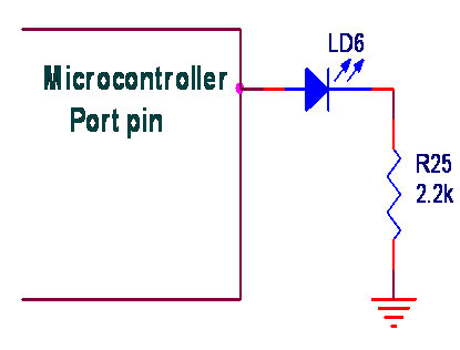
Fig. 1 shows how to interface the LED to microcontroller. As you can see the Anode is connected through a resistor to GND & the Cathode is connected to the Microcontroller pin. So when the Port Pin is HIGH the LED is OFF & when the Port Pin is LOW the LED is turned ON.
Interfacing LED with LPC2148
We now want to flash a LED in LPC2148 Starter Board. It works by turning ON a LED & then turning it OFF & then looping back to START. However the operating speed of microcontroller is very high so the flashing frequency will also be very fast to be detected by human eye.
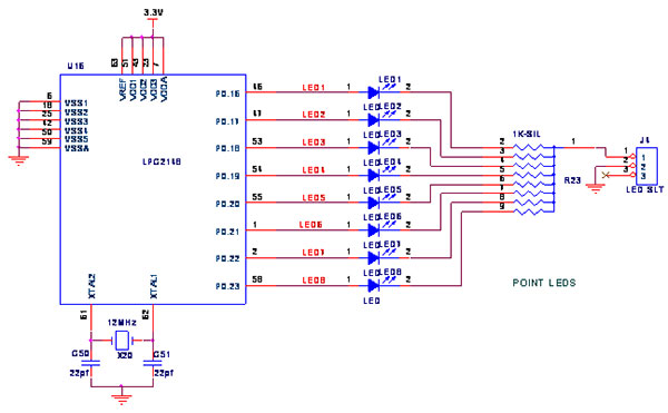
The ARM7 LPC2148 Starter Board has eight numbers of point LEDs, connected with I/O Port lines (P0.16 – P0.23) to make port pins high.
Pin Assignment with LPC2148
Circuit Diagram to Interface LED with LPC2148
Source Code
The Interfacing LED with LPC2148 program is very simple and straight forward, that uses a delay procedure loop based software delay. In C programs you cannot be sure of delay, because it depends on compiler how it optimizes the loops as soon as you make changes in the options the delay changes.
C Program to switch ON and OFF LED using LPC2148
#include//
Define LPC2148 Header File
#define led IOPIN0//
Define LED to Port0
#define tled IO0DIR//
Define Port0 as output void delay(int x);
{
void main()
PINSEL2 = 0x00000000;
//Define port lines as GPIO tled = 0x00FF0000;
// Define P0.16 – P0.23 as O/P led = 0x00000000;
// Define P0.16 – P0.23 as zero while(1)
// Loop forever { led = 0x00FF0000;
// Turn ON P0.16 – P0.23 delay(2000);
led = 0x00000000;// Turn OFF P0.16 – P0.23 delay(2000);
}
}
void delay(int x)
{
unsigned int k,l;
for(k = x;k > 0;k--)
for(l = 0;l < x;l++);
}
To compile the above C code you need the KEIL software. They must be properly set up and a project with correct settings must be created in order to compile the code. To compile the above code, the C file must be added to the project.
In Keil, you want to develop or debug the project without any hardware setup. You must compile the code for generating HEX file. In debugging Mode, you want to check the port output without LPC2148 Starter Board.
The Flash Magic software is used to download the hex file into your microcontroller IC LPC2148 through UART0.
Testing the LED with LPC2148
Give +3.3V power supply to LPC2148 Starter Board; the LED is connected with microcontroller LPC2148 Starter Board. When the program is downloading into LPC2148 in Starter Board, the LED output is working that the LED is ON some time period and the LED is OFF some other time period.
If you not reading any output from LED, then you just check the jumper connections & check the LED is working. Otherwise you just check it with debugging mode in Keil. If you want to see more details about debugging just see the videos in below link.
☞How to Create and Debug a Project in Keil .
General Information
☞For proper working use the components of exact values as shown in Circuit file. Wherever possible use new components.
☞Solder everything in a clean way. A major problem arises due to improper soldering, solder jumps and loose joints.
☞Use the exact value crystal shown in schematic.
☞More instructions are available in following articles,