How to Interface GLCD with LPC2148 ARM7 Development board
The ARM7 LPC2148 Development board is specifically designed to help students to master the required skills in the area of embedded systems. The kit is designed in such way that all the possible features of the microcontroller will be easily used by the students. The kit supports in system programming (ISP) which is done through serial port.
NXP’s ARM7 (LPC2148), ARM Primer Kit is proposed to smooth the progress of developing and debugging of various designs encompassing of High speed 32-bit Microcontrollers.
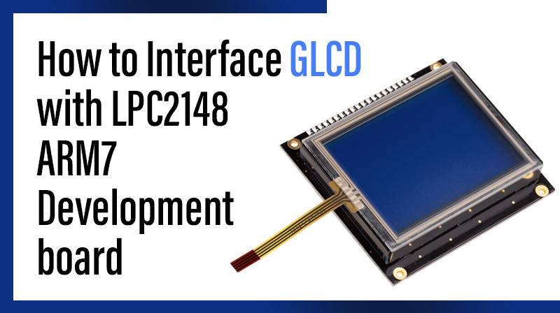
GLCD (Graphical Liquid Crystal Display)
The Graphics LCD as the name suggests is a type of LCD which can display graphics. The graphical representation of any data presents good understanding than just characters. More user friendly applications can be designed by using the graphical LCDs.
Interfacing GLCD
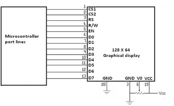
Fig. 1 shows how to interface the GLCD to microcontroller. The 128X64 Graphical LCD interfaces to adjust contrast through trim pot. The GLCD needed to create 8-bit interface; 8 data bits (D0 – D7), three control lines, address bit (RS), read/write bit (R/W) and control signal (E), Page Select (CS).
Interfacing GLCD with LPC2148
Display a text in LPC2148 Development Board by using GLCD module. The ARM7 LPC2148 Development Board has numbers of GLCD connections, connected with I/O Port lines (P0.0, P0.1, P0.4 – P0.6 && P0.8 – P0.15) to make GLCD display.
Pin Assignment with LPC2148
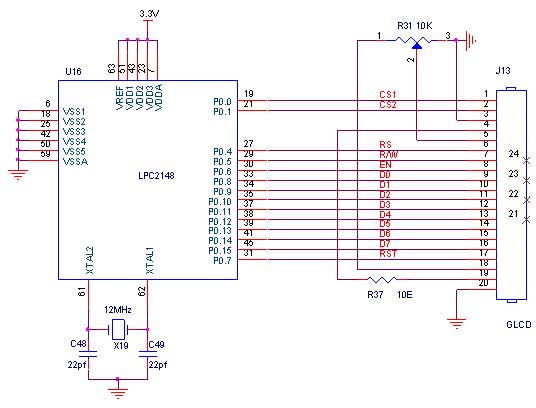
Circuit Diagram to Interface GLCD with LPC2148
Source Code
The Interfacing GLCD with LPC2148 program is very simple and straight forward, that display a text in 128 X 64 GLCD module. Some delay is occurring when a single command / data is executed. In C programs you cannot be sure of delay, because it depends on compiler how it optimizes the loops as soon as you make changes in the options the delay changes.
C Program to display a text in GLCD using LPC2148
***************************************************************************************
Title : Program to GLCD display
***************************************************************************************
#include
#include "GLCD.H"
#include "GLCDBMP.H"
#define RST 7 void main()
{
PINSEL0 = 0;
PINSEL1 = 0;
IODIR0 = 0x0000FFFF;
GLCD_Init (&IO0PIN, 8);
while(1)
{
Delay();
Delay();
Delay();
Delay();
GLCD_Draw (&IO0PIN, 8, PAN_LOGO);
Delay();
Delay();
Delay();
Delay();
GLCD_Draw(&IO0PIN, 8, BMP_IMG);
}
}
void Delay()
{
unsigned int i,j;
for(i=0;i<25;i++)
for(j=0;j<300;j++);
}
To compile the above C code you need the KEIL software. They must be properly set up and a project with correct settings must be created in order to compile the code. To compile the above code, the C file must be added to the project.
In Keil, you want to develop or debug the project without any hardware setup. You must compile the code for generating HEX file. In debugging Mode, you want to check the port output without microcontroller Primer Board.
The Flash Magic software is used to download the hex file into your microcontroller through UART0.
Testing the Graphical LCD Module with LPC2148
Give +3.3V power supply to LPC2148 Development Board; the Graphical LCD is connected with microcontroller LPC2148 Board. When the program is downloading into LPC2148 in Primer Board, the screen should show the image output.
If you not reading any output from Graphical LCD, then you just check the jumper connections & adjust the trim pot level. Otherwise you just check it with debugging mode in Keil. If you want to see more details about debugging just see the videos in below link.
General Information
- For proper working use the components of exact values as shown in Circuit file. Wherever possible use new components.
- Solder everything in a clean way. A major problem arises due to improper soldering, solder jumps and loose joints.
- Use the exact value crystal shown in schematic.
- More instructions are available in following articles,