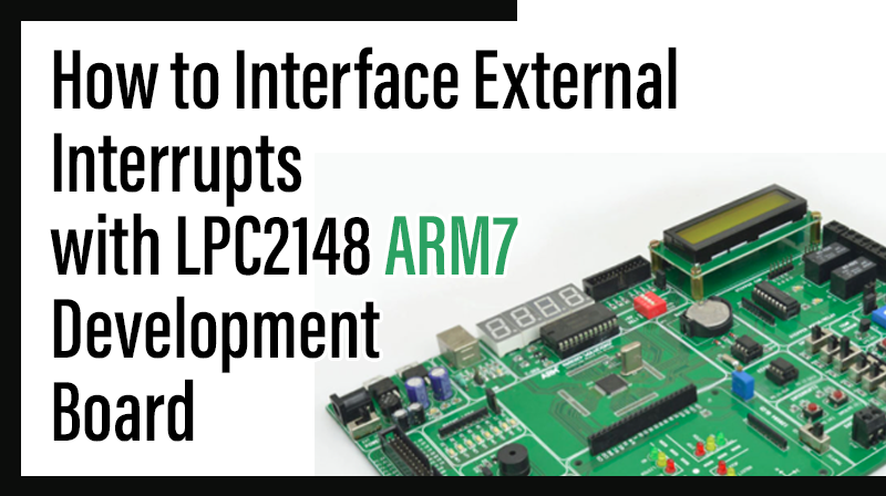
How to Interface External Interrupts with LPC2148 ARM7 Development Board
The ARM7 LPC2148 Development board is specifically designed to help students to master the required skills in the area of embedded systems. The kit is designed in such way that all the possible features of the microcontroller will be easily used by the students. The kit supports in system programming (ISP) which is done through serial port.
NXP’s ARM7 (LPC2148), ARM Development Kit is proposed to smooth the progress of developing and debugging of various designs encompassing of High speed 32-bit Microcontrollers.
External Interrupts
An interrupt caused by an external source such as the computer operator, external sensor or monitoring device, or another computer. Interrupts are special events that require immediate attention.
Interfacing External Interrupts
Fig. 1 shows how to interface the External Interrupt to microcontroller. Interrupts cause the processor to cease the running task to serve a special task for which the interrupt event had occurred. After the special task is over, the processor resumes performing the original task.
The processor can also serve these events by polling method. But polling is an inefficient technique as compared to interrupts. In the polling method, the processor has to continuously wait for the event signal. Thus it always remains busy using extra resources.

Interfacing External Interrupts with LPC2148
When an external interrupt signal is occured in LPC2148 Development Board, the message “LOW” will be displayed on PC. The Interrupt signal is occurred by using switches. When the switch is pressed to LOW, then the external interrupt is occurred.
The Vectored Interrupt Controller (VIC) takes 32 interrupt request inputs and programmable assigns them into 3 categories, FIQ, vectored IRQ, and non-vectored IRQ.
The ARM7 LPC2148 Development Board has two numbers of External Interrupts, connected with I/O Port lines (P0.14 & P0.15) as switches.
Pin Assignment with LPC2148
Circuit Diagram to Interface Ext-Interrupt with LPC2148

Source Code
The Interfacing External Interrupt with LPC2148 program is very simple and straight forward, that accessed by using switches. When the two external interrupts occurring, some messages are displayed in PC through serial port at 9600 baud rate. The C programs are written in Keil software.
C Program to interface Ext-Interrupt using LPC2148
***************************************************************************************
Title : Program to interface an external Interrupt
*****************************************************************************************
#include

// Define LPC2148 Header File
#include
int volatile EINT1 = 0;
int volatile EINT2 = 0;
void ExtInt_Serve1(void)__irq;
void ExtInt_Serve2(void)__irq;
void ExtInt_Serve1(void)__irq
{
++EINT1;
EXTINT |= 2;
VICVectAddr = 1;
}
void ExtInt_Serve2(void)__irq
{
++EINT2;
EXTINT |= 4;
VICVectAddr = 0;
}
void main(void)
{
Serial_Init();
ExtInt_Init1();
//Initialize Interrupt 1 ExtInt_Init2();
//Initialize Interrupt 2 putchar(0x0C);
printf ("***************** External Interrupt Demo ***************************\n\n\r");
DelayMs(100);
printf (">>> Press Interrupt Keys SW2(INT1) and SW3(INT2) for Output... \n\n\n\r");
DelayMs(100);
while(1)
{
DelayMs(500);
printf("INT1 Generated : %d | INT2 Generated : %d \r", EINT1, EINT2);
DelayMs(500);
}
}
void ExtInt_Init2(void)
{
EXTMODE |= 4;
//Edge sensitive mode on EINT2 EXTPOLAR = 0;
//Falling Edge Sensitive PINSEL0 |= 0x80000000;
//Enable EINT2 on P0.15 VICVectCntl1 = 0x20 | 16;
// 16 is index of EINT2 VICVectAddr1 = (unsigned long) ExtInt_Serve2;
VICIntEnable |= 1<<16;
//Enable EINT2
}
void ExtInt_Init1(void)
{
EXTMODE |= 2;
//Edge sensitive mode on EINT1 EXTPOLAR = 0;
//Falling Edge Sensitive PINSEL0 |= 0x20000000;
//Enable EINT2 on P0.14 VICVectCntl0 = 0x20 | 15;
//15 is index of EINT1 VICVectAddr0 = (unsigned long) ExtInt_Serve1;
VICIntEnable |= 1<<15;
//Enable EINT1
}
void Serial_Init(void)
{
PINSEL0 |= 0X00000005;
//Enable Txd0 and Rxd0 U0LCR = 0x00000083;
//8-bit data,1-stop bit U0DLL = 0x00000061;
//XTAL = 12MHz U0LCR = 0x00000003;
//DLAB = 0;
}
void DelayMs(unsigned int count)
{
unsigned int i,j;
for(i=0;i<count;i++)
{
for(j=0;j<1000;j++);
}
}
To compile the above C code you need the KEIL software. They must be properly set up and a project with correct settings must be created in order to compile the code. To compile the above code, the C file must be added to the project.
In Keil, you want to develop or debug the project without any hardware setup. You must compile the code for generating HEX file. In debugging Mode, you want to check the port output without LPC2148 Development Board.
The Flash Magic software is used to download the hex file into your microcontroller IC LPC2148 through UART0.
Testing the External Interrupts with LPC2148
Give +3.3V power supply to LPC2148 Development Board; the serial cable is connected between the LPC2148 Development Board and PC. Open the Hyper Terminal screen, select which port you are using and set the default settings. Now the screen should show which external interrupt is selected.
When you pressed the external interrupt key, the screen should update which interrupt is now pressed. The external Interrupts are controlled by using switches. If any data is not coming in Hyper Terminal, then you just check the serial cable is working or not. Otherwise you just check the code with debugging mode in Keil. If you want to see more details about debugging just see the videos in below link.
☞ How to Create & Debug a Project in Keil.
General Information
☞For proper working use the components of exact values as shown in Circuit file. Wherever possible use new components.
☞Solder everything in a clean way. A major problem arises due to improper soldering, solder jumps and loose joints.
☞More instructions are available in following articles,
How to Interface UART with LPC2148 ARM7 Development Board
How to Interface Keypad with LPC2148 ARM7 Development Board