
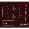
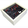


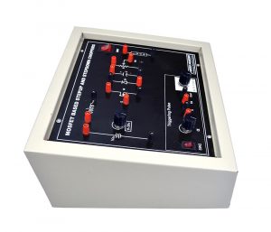
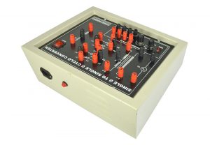
IGBT Based Single Phase Inverter
₹25,000.00 Exc Tax
IGBT Based Single Phase Inverter
Out of stock
Description
Features
- All Components are terminated with a connector for the study of Students.
- One no of potentiometer is provided to vary the Frequency.
- Inbuilt Power supply for Inverter and triggering pulse.
- Inbuilt Resistive Load is provided.
- Power ON indication Switches for Power circuit and Triggering circuit.
- All the important points are terminated with banana connector for monitor/measure/ study the signals using any one of measuring equipments.
Experiments
- Design of Single Phase Inverter using IGBT.
Technical Specification
- Kit Working voltage (220-240)VAC
- Input Voltage 30VDC
- Output Current 1A
- Output Voltage 30VAC ±2V
- Input Frequency 50Hz
- Output Frequency 10-50Hz
Bundle Contents
- IGBT Based single phase inverter kit
- Patch cards
- 6A power supply card
- 1A Fuse
- User Manual of Kit
Accessories
- RHEOSTAT R-LOAD
- Value 0-100 Ohm 2 A
Additional information
| Weight | 10.000000 kg |
|---|
Related products
-
- Out of StockRead more

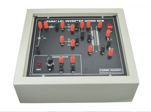
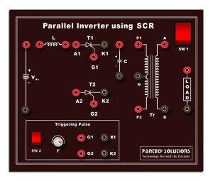
- Power Electronics
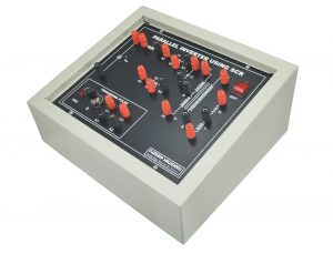
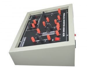
Parallel Inverter
- Call for Price
-

-

-

-

-

-
-
- Out of StockRead more

- Power Electronics
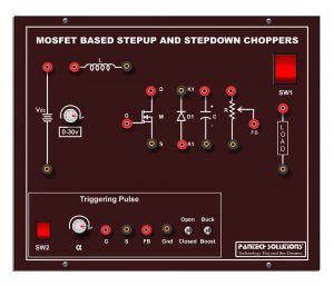
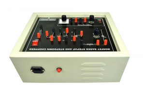
Step Down and Step Up Chopper
- ₹19,500.00 Exc Tax
-

-

-

-

-

-
-
- Out of StockRead more

- Power Electronics
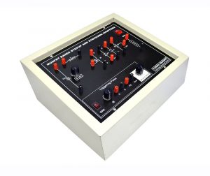
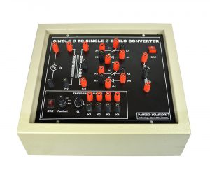
Cyclo Converter
- ₹21,500.00 Exc Tax
-

-

-

-
-

-


Reviews
There are no reviews yet.