How to Interface LCD with dsPIC30F4011 – dsPIC Development Board
The DsPIC30F4011 Development Board is specifically designed to help students to master the required skills in the area of embedded systems. The kit is designed in such way that all the possible features of the microcontroller will be easily used by the students. The kit supports in system programming (ISP) which is done through USB port.
Microchip’s dsPIC30F (dsPIC30F4011), Development Kit is proposed to smooth the progress of developing and debugging of various designs encompassing of High speed 16-bit Microcontrollers.
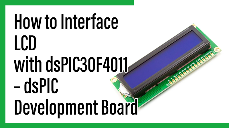
LCD (Liquid Crystal Display)
Liquid Crystal Display also called as LCD is very helpful in providing user interface as well as for debugging purpose. A liquid crystal display (LCD) is a flat panel display that uses the light modulating properties of liquid crystals (LCs). LCD Modules can present textual information to user.
Interfacing LCD
Fig. 1 shows how to interface the LCD to microcontroller. The 2×16 character LCD interface card with supports both modes 4-bit and 8-bit interface, and also facility to adjust contrast through trim pot. In 4-bit interface 7 lines needed to create 4-bit interface; 4 data bits (D0 – D3), three control lines, address bit (RS), read/write bit (R/W) and control signal (E).
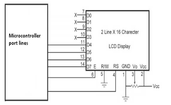
A 16×2 LCD means it can display 16 characters per line and there are 2 such lines. In this LCD each character is displayed in 5×7 pixel matrix. This LCD has two registers.
1. Command/Instruction Register – stores the command instructions given to the LCD. A command is an instruction given to LCD to do a predefined task like initializing, clearing the screen, setting the cursor position, controlling display etc.
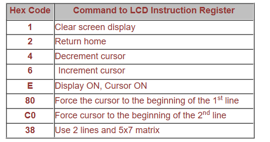
2. Data Register – stores the data to be displayed on the LCD. The data is the ASCII value of the character to be displayed on the LCD. Commonly used Command codes:
Programming the LCD
☞Data pin8 (DB7) of the LCD is busy flag and is read when R/W=1 & RS=0. When busy flag=1, it means that LCD is not ready to accept data since it is busy with internal operations. Therefore before passing any data to LCD, its command register should be read and busy flag should be checked.
☞To send data on the LCD, data is first written to the data pins with R/W = 0 (to specify the write operation) and RS = 1 (to select the data register). A high to low pulse is given at EN pin when data is sent. Each write operation is performed on the positive edge of the Enable signal.
☞To send a command on the LCD, a particular command is first specified to the data pins with R/W = 0 (to specify the write operation) and RS = 0 (to select the command register). A high to low pulse is given at EN pin when data is sent.
Interfacing 4 bit LCD with dsPIC
We now want to display a text in dsPIC Development Board by using 4 bit LCD module.
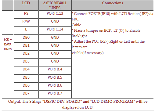
The DsPIC30F4011 Development Board has seven numbers of LCD connections are needed to create 4-bit interface; connected with 4 data bits (PORTB.4 – PORTB.7, D4-D7), address bit (RS-PORTC.13), read/write bit (R/W-GND) and control signal (E-PORTC.14) to make LCD display.
Pin Assignment with dsPIC30F4011
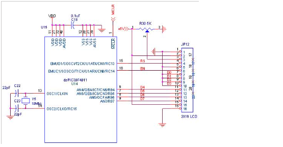
Circuit Diagram to Interface 4 bit LCD with dsPIC
Source Code
The Interfacing 4 bit LCD with dsPIC program is very simple and straight forward, which display a text in 2 X 16 LCD module using 4 data lines only. Some delay is occurring when a single command / data is executed.
C Program to display a text in 4 bit LCD using dsPIC
#include "p30f4011.h"
#include "delay.c"
_FOSC(CSW_FSCM_OFF & XT);
_FWDT(WDT_OFF);
_FBORPOR(PBOR_ON & MCLR_EN);
_FGS(CODE_PROT_OFF);
#define RS LATCbits.LATC13
//There is no RW connection
#define EN LATCbits.LATC14
#define DATA LATB unsigned int i,temp; void lcd_init(void);
void lcd_command(unsigned char);
void lcd_data(unsigned char);
void Lcdtog();
int main()
{
unsigned char Lcd_LINE1[]={"DSPIC DEV. BOARD"};
unsigned char Lcd_LINE2[]={"LCD DEMO PROGRAM"};
Delay_ms4M(50);
lcd_init();
Delay_ms4M(300);
while(1)
{
lcd_command(0x01);
Delay_ms4M(1000);
lcd_command(0x80);
for(i=0;Lcd_LINE1[i]!='\0';i++)
{
lcd_data(Lcd_LINE1[i]);
Delay_ms4M(500);
}
lcd_command(0xc0);
for(i=0;Lcd_LINE2[i]!='\0';i++)
{
lcd_data(Lcd_LINE2[i]);
Delay_ms4M(500);
}
Delay_ms4M(5000);
}
return 0;
}
void lcd_init()
{
ADPCFG = 0xFFFF;
TRISC = 0;
TRISB = 0;
PORTB = 0;
LATB = 0;
Delay_ms4M(100);
lcd_command(0x33);
lcd_command(0x32);
lcd_command(0x28);
lcd_command(0x0C);
lcd_command(0x06);
lcd_command(0x01);
}
void lcd_command(unsigned char cmd)
{
RS=0;
DATA=(cmd & 0xf0);
EN=1;
EN=0;
DATA=((cmd << 4) & 0xf0);
EN=1;
EN=0;
Delay_ms4M(5);
}
void lcd_data(unsigned char data)
{
RS=1;
DATA=(data & 0xf0);
EN=1;
EN=0;
DATA=((data << 4) & 0xf0);
EN=1;
EN=0;
Delay_ms4M(5);
}
To compile the above C code you need the Mplab software & Microchip C30 Compiler. They must be properly set up and a project with correct settings must be created in order to compile the code. To compile the above code, the C file must be added to the project.
In Mplab, you want to develop or debug the project without any hardware setup. You must compile the code for generating HEX file. In debugging Mode, you want to check the port output without microcontroller Board.
The PICKIT2 is used to download the hex file into your microcontroller through USB.
Testing the LCD Module with dsPIC30F4011
Give +12V power supply to DsPIC30F4011 Development Board; the LCD is connected with microcontroller DsPIC30F4011 Development Board. When the program is downloading into dsPIC30F4011 in Development Board , the screen should show the text messages.
If you are not reading any text from LCD, then you just check the jumper connections & adjust the trim pot level. Otherwise you just check it with debugging mode in Mplab. If you want to see more details about debugging just see the videos in below link.
☞How to create & Debug a Project in Mplab using dsPIC30F.
General Information
☞For proper working use the components of exact values as shown in Circuit file. Use new components.
☞Solder everything in a clean way. A major problem arises due to improper soldering, solder jumps and loose joints.
☞Use the exact value crystal shown in schematic.
☞More instructions are available in following tutorials,