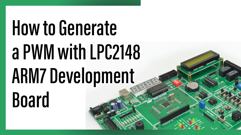
How to Generate a PWM with LPC2148 ARM7 Development Board
The ARM7 LPC2148 Development board is specifically designed to help students to master the required skills in the area of embedded systems. The kit is designed in such way that all the possible features of the microcontroller will be easily used by the students. The kit supports in system programming (ISP) which is done through serial port.
NXP’s ARM7 (LPC2148), ARM Development Kit is proposed to smooth the progress of developing and debugging of various designs encompassing of High speed 32-bit Microcontrollers.
PWM (Pulse Width Modulation)
Pulse width modulation (PWM) is a powerful technique for controlling analog circuits with a processor’s digital outputs. PWM is employed in a wide variety of applications, ranging from measurement and communications to power control and conversion.
Interfacing PWM
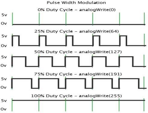
Figure 1 shows four different PWM signals. One is PWM output at a 25% duty cycle. That is, the signal is on for 25% of the period and off the other 75%. Next shows PWM output at 50%, 75% and 100% duty cycles, respectively. These three PWM outputs encode three different analog signal values, at 10%, 50%, and 90% of the full strength.
Interfacing PWM with LPC2148
Generate a PWM in LPC2148 Development Board at a particular frequency. Pulse Width Modulation is a technique for getting analog results with digital means.
Digital control is used to create a square wave, a signal switched between on and off. This on-off pattern can simulate voltages in between full on (5 Volts) and off (0 Volts) by changing the portion of the time the signal spends on versus the time that the signal spends off. The duration of “on time” is called the pulse width. To get varying analog values, you change, or modulate, that pulse width.
Pin Assignment with LPC2148
Circuit Diagram to Interface PWM with LPC2148

Source Code
The Interfacing PWM with LPC2148 program is very simple and straight forward, which generates a pulse pattern in a particular frequency. An ADC signal is used to varying the duty cycle of PWM signal. The C program is written in Keil software.
C Program to generate PWM in LPC2148
***************************************************************************************
Title : Program to generate PWM
****************************************************************************************
#include // Define LPC2148 Header File
#include
void PWM0_isr(void) __irq
{
PWMIR |= 0x00000001; // Clear match0 interrupt
VICVectAddr = 0x00000000;
}
int main (void)
{
unsigned long val;
unsigned long oldval = 0;
VPBDIV = 0x02;
PINSEL0 |= 0x00050000;
PINSEL1 = 0x15400000;
init_PWM();
U1LCR = 0x83;
U1DLL = 0xC3;
U1LCR = 0x03;
AD0CR = 0x00230608; // Setup A/D: 10-bit AIN0 @3MHz
AD0CR |= 0x01000000; // Start A/D Conversion
while (1)
{
// Loop forever do
{
val = AD0GDR; /* Read A/D Data Register */
}
while ((val & 0x80000000) == 0);
val = ((val >> 6) & 0x3FF);
// Extract AIN0 Value Delay ();
Delay();
if (val != oldval)
{
PWMMR2 = val;
PWMLER = 0xF;
oldval = val;
printf ("Val : %4d \n\r", val);
}
}
}
void init_PWM (void)
{
VICVectAddr8 = (unsigned)PWM0_isr; //PWM ISR vec.addr
VICVectCntl8 = 0x00000028; // Set channel
VICIntEnable = 0x00000100; // Enable the interrupt
PINSEL0 |= 0x00008008; // Enable P0.7&P0.1-PWM
PWMPR = 0x00000000; // Load prescaler
PWMPCR = 0x00000C0C; /* PWM channel 2 & 3 double edge control*/
PWMMCR = 0x00000003; // reset the counter
PWMMR0 = 0x400; // set dutycycle is sixteen ticks
PWMMR1 = 0; // rising edge of PWM2– 100 tricks
PWMMR2 = 0x200; // falling edge of PWM2- 200 ticks
PWMMR3 = 0x100; // rising edge of PWM2– 100 tricks
PWMLER = 0xF; // shadow latch for match 1 – 3
PWMTCR = 0x00000002; // Reset counter and prescaler
PWMTCR = 0x00000009; // release counter from reset
}
void Delay ()
{
unsigned int i,j;
for (i=0;i<250;i++)
for (j=0;j<700;j++);
}
To compile the above C code you need the KEIL software. They must be properly set up and a project with correct settings must be created in order to compile the code. To compile the above code, the C file must be added to the project.
In Keil, you want to develop or debug the project without any hardware setup. You must compile the code for generating HEX file. In debugging Mode, you want to check the port output without LPC2148 Development Board.
The Flash Magic software is used to download the hex file into your microcontroller IC LPC2148 through UART0.
Testing the PWM with LPC2148
Give +3.3V power supply to LPC2148 Development Board; the PWM port line is connected in LPC2148 Development Board. When the program is downloading into LPC2148 in Development Board,the PWM output is generating at a particular frequency.
If you are not reading any PWM output, then you just check the jumper connections. Otherwise you just check it with debugging mode in Keil. If you want to see more details about debugging just see the videos in below link.
☞How to Create & Debug a Project in Keil.
General Information
☞For proper working use the components of exact values as shown in Circuit file. Wherever possible use new components.
☞Solder everything in a clean way. A major problem arises due to improper soldering, solder jumps and loose joints.
☞Use the exact value crystal shown in schematic.
☞More instructions are available in following articles,