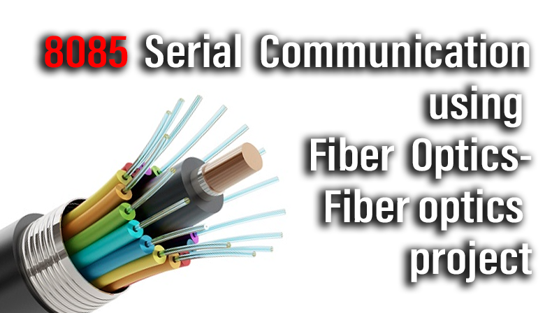
8085 Serial Communication using Fiber Optics-Fiber optics project
Aim
To Study the 8085 kit to kit communication using Optic Digital link.
Apparatus Required
- Fiber Optics Digital Transmitter Module – 01
- Fiber Optics Digital Receiver Module – 01
- Plastic Fiber cable 1 meter – 01
- PS 8085 kit – 02
- Adapter +15V/ DC – 02
- Patch Chords – 04
- PC to PC cable – 02
Theory
Kit to Kit communication
Fiber optic digital link was used to transmit and receive the data from one place another place .In this digital link will be supporting 1Mbd speed data communication. It will be act as an optical data modem. So we can use this digital link system in various sectors. And this digital link was used RS 232 serial port for communication.
Transmitter
The heart of the transmitter is a light source. The major function of a light source is to convert an information signal from its electrical form into light. Today’s fiber-optic communications systems use, as a light source, either light-emitting diodes (LEDs) or laser diodes (LDS). Both are miniature semiconductor devices that effectively convert electrical signals into light. They need power-supply connections and modulation circuitry. All these components are usually fabricated in one integrated package
This type LEDs needs external Driver circuits. Here we used IC 75451 for drive the LED.
Optical fiber
The transmission medium in fiber-optic communications systems is an optical fiber. The optical fiber is the transparent flexible filament that guides light from a transmitter to a receiver. An optical information signal entered at the transmitter end of a fiber – optic communications system is delivered to the receiver end by the optical fiber.
Model Diagram for Plastic Fiber cable
This is multi mode plastic fiber cable, in this fiber cable core diameter 1000 micron and fiber cladding index 1.402.
Receiver
The key component of an optical receiver is its photo detector. The major function of a photo detector is to convert an optical information signal back into an electrical signal (Photocurrent). The photo detector in today’s fiber – optic communications systems is a semiconductor photodiode (PD). This miniature device is usually fabricated together with its electrical circuitry to from an integrated package that provides power-supply connections and signal amplification.
In this type Photo Diode have internal driver circuits. So no need any external driver.
Procedure
- Connect +15V adapter to both transmitter and receiver module.
- Switch (sw1) ON the transmitter Module, 8085 kits and receiver module (sw1).
- Connect PC to PC cable between 8085Kit 1 to transmitter Module P5 connector and receiver module P8 connecter to 8085Kit 2.
- Connect the 1 m Plastic fiber cable between transmitter Module LED to receiver module Photo Diode.
- Connect P7 and P9 using patch chord at transmitter Module.
- Connect P3 and P7 using patch chord at receiver module.
- Now type the transmitter program in transmitter side kit and receiver program in receiver side 8085 Kit.
8085 Transmitter Program
| Address | Opcode | Mnemonics |
| 9100 | 21 00 92 | LXI H,9200 |
| 9103 | 3E B6 | MVI A,B6 |
| 9105 | D3 23 | OUT 23 |
| 9107 | 3E 40 | MVI A,40 |
| 9109 | D3 22 | OUT 22 |
| 910B | 3E 01 | MVI A,01 |
| 910D | D3 22 | OUT 22 |
| 910F | 0E 05 | RELOAD : MVI C,05 |
| 9111 | DB 01 | CHECK : IN 01 |
| 9113 | E6 04 | ANI 04 |
| 9115 | CA 11 91 | JZCHECK |
| 9118 | 7E | MOV A,M |
| 9119 | D3 00 | OUT 00 |
| 911B | 23 | INX H |
| 911C | FE 3F | CPI 3F |
| 911E | C2 0F 91 | JNZ RELOAD |
| 9121 | 0D | DCR C |
| 9122 | C2 11 91 | JNZ CHECK |
| 9125 | CF | RST 1 |
8085 Receiver Program
| Address | Opcode | Mnemonics |
| 9100 | 21 00 92 | LXI H,9200 |
| 9103 | 3E B6 | MVI A,B6 |
| 9105 | D3 23 | OUT 23 |
| 9107 | 3E 40 | MVI A,40 |
| 9109 | D3 22 | OUT 22 |
| 910B | 3E 01 | MVI A,01 |
| 910D | D3 22 | OUT 22 |
| 910F | 0E 05 | RELOD : MVI C,05 |
| 9111 | DB 01 | CHECK : IN 01 |
| 9113 | E6 02 | ANI 04 |
| 9115 | CA 11 91 | JZ CHECK |
| 9118 | DB 00 | IN 00 |
| 911A | 77 | MOV M,A |
| 911B | 23 | INX H |
| 911C | FE 3F | CPI 3F |
| 911E | C2 0F 91 | JNZ RELOAD |
| 9121 | 0D | DCR C |
| 9122 | C2 11 91 | JNZ CHEAK |
| 9125 | CF | RST 1 |
| 9126 | CF | RST 1 |
☞First execute the receiver side 8085 kit.
☞Give the transmitting data from 9200 address and execute the transmitter side 8085 kit.
☞Now received data verified from 9200 address in receiver side 8085 kit.


