Band width Measurement of Fiber Optic Analog Link
Aim
To Study the Band width Measurement of Fiber Optic Analog Link
Apparatus Required
- Fiber Optics Analog Transmitter Module – 01
- Fiber Optics Analog Receiver Module – 01
- Plastic Fiber cable 1 meter – 01
- CRO – 01
- Function Generator (1MHz) – 01
- Adapter +15V/ DC – 02
- Patch Chords – 06
Theory
System Band width
If the fiber optical analog link system Bandwidth means, the analog link system supporting range. It will be defined the system supporting minimum and maximum frequency range. The well communication systems have higher Bandwidth range and that system ready to transmit and receive higher range of signal in broad bandwidth.
Transmitter
The heart of the transmitter is a light source. The major function of a light source is to convert an information signal from its electrical form into light. Today’s fiber-optic communications systems use, as a light source, either light-emitting diodes ( LEDs) or laser diodes (LDS). Both are miniature semiconductor devices that effectively convert electrical signals into light. They need power-supply connections and modulation circuitry. All these components are usually fabricated in one integrated package. Transistor based driver circuit need for this type LEDs.
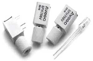
Optical fiber
The transmission medium in fiber-optic communications systems is an optical fiber. The optical fiber is the transparent flexible filament that guides light from a transmitter to a receiver. An optical information signal entered at the transmitter end of a fiber – optic communications system is delivered to the receiver end by the optical fiber.
Model Diagram for Plastic Fiber cable
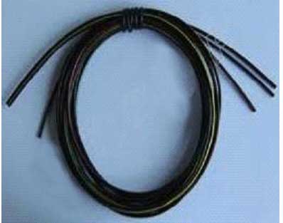
This is multi mode plastic fiber cable, in this fiber cable core diameter 1000 micron and fiber cladding index 1.402.
Receiver
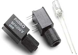
The key component of an optical receiver is its photo detector. The major function of a photo detector is to convert an optical information signal back into an electrical signal (Photocurrent). The photo detector in today’s fiber – optic communications systems is a semiconductor photodiode (PD). This miniature device is usually fabricated together with its electrical circuitry to from an integrated package that provides power-supply connections and signal amplification.
Procedure
- ☞Connect +15V adapter to both transmitter and receiver module
- ☞Switch (sw1) ON the transmitter Module, CRO and function generator.
- ☞Connect the BNC to BNC cable between function generator and Ext Analog input P2 connecter.
- ☞Now check the P3 test point and get sine wave output on CRO.
- ☞Set the sine wave output 1 Vpp (Vin).
- ☞Connect P3 and P8 using patch chord.
- ☞Connect P9 and P10 using patch chord.
- ☞Connect the 1 m Plastic fiber cable between transmitter module LED to receiver module Photo Diode.
- ☞Switch (sw1) ON the receiver Module.
- ☞Connect P2 and P4 using patch chord.
- ☞Connect P5 and P6 using patch chord.
- ☞Check the analog output (Vo) on test point P7.
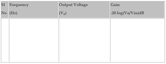
- ☞Vary the function generator frequency range 50 Hz to 500 KHz and note down the analog output Amplitude.
- ☞Tabulate the readings in bellow tabular Colum.
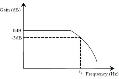
- ☞Plate the gain vs frequency graph.
- ☞And find the optical analog system bandwidth.
Tabular Column
Model Graph